
Fatigue is the Initiation, formation and propagation of cracks in a material due to cyclic loads. The failure occurs due to the cyclic nature of the load which causes microscopic material imperfections to grow into a macroscopic crack. This phenomenon mainly happens but due to multiple load cycles which causes components to lose their strength and get tired, hence it is called fatigue.
Once a fatigue crack has initiated, it grows a small amount with each loading cycle and it will continue to grow until it reaches a critical size, which occurs when the stress intensity factor of the crack exceeds the fracture toughness of the material, producing rapid propagation and typically complete fracture of the structure.
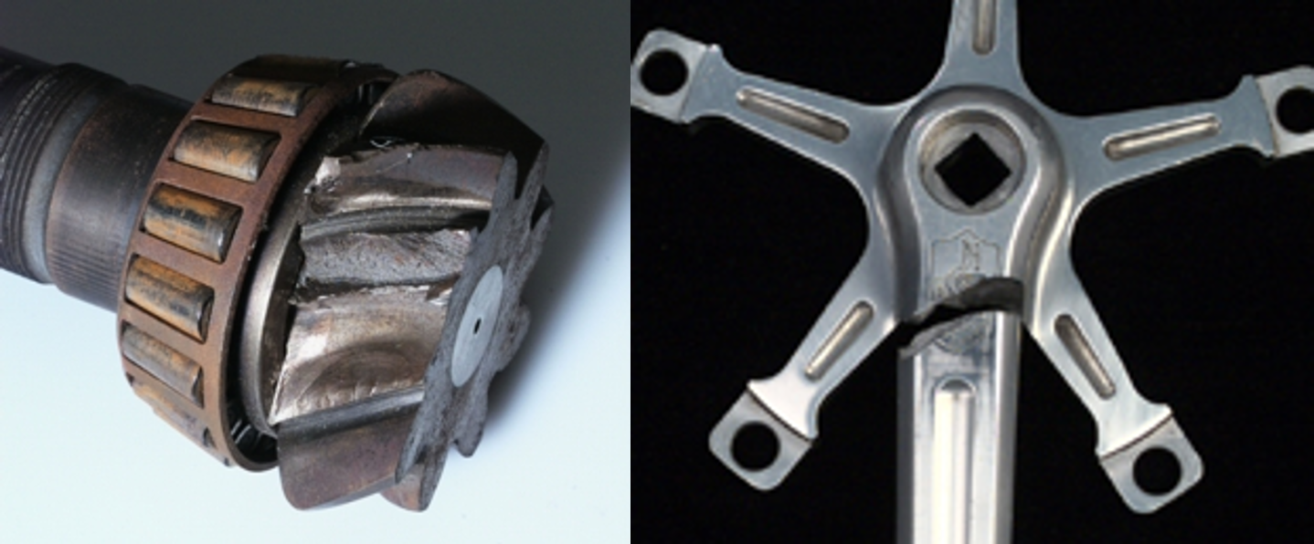
Fatigue cracks normally initiate at stress concentrations, structural discontinuities. Fatigue cracks can also propagate from existing macroscopic cracks, such as weld defects. Almost all structural components are subjected to fluctuating loads at one time or another.
Fatigue Life:
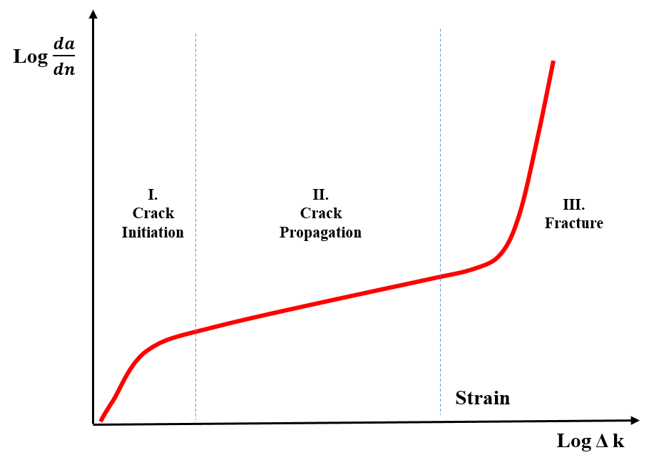
It is defined as the number of cycles that a component can withstand before fatigue failure occurs. Figure 2 depicts the various fatigue life stages.
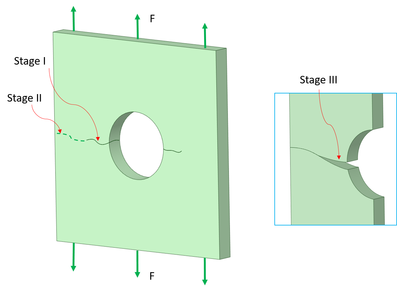
There are three stages of fatigue fracture: Crack initiation, Crack propagation and Final rupture. Fatigue failures, both for high and low cycles follows the same basic step process of Crack initiation stage I, stage II Crack Propagation, and step III finally ultimate failure. Refer figure 3 for stages of fatigue failure on plate with hole in central under pull force on both end.
Crack Initiation:
This phase includes crack nucleation and small crack growth. This is the beginning process, in which cracks initiate at very small material microstructures or at areas with high void density. At these tiny locations, the cracks lead to persistent slip bands that propagate along the maximum shear plane (45 degree from the direction of the applied load) under cyclic loads (alternating stress). These locations are undetectable with naked eyes and result in highly localized stress concentrations.
Crack Propagation:
In this stage, once cracks reach a critical size, micro cracks grow and transverse 2-3 grain boundaries large compared to material microstructure. The stress concentration at these locations results in plastic stresses at the crack tip locations. These cyclic plastic stresses start orienting perpendicular to maximum principal stress and thus micro-crack slowly grows over an indefinable area of fatigue fracture.
Fatigue Failure:
In this stage, the crack which developed in the second stage, if continues to grow due to existing sufficient energy will continue until tensile failure occurs.
For example if the test specimen went under crack nucleation and growth stage and propagation of crack continues, it gradually reduces of the cross-sectional area of test specimen and eventually weakens the part so that final, complete fracture can occur with only one more load application. The fracture mode may be either ductile or brittle or any combination depending upon the metal concerned, the stress level, the environment, etc.
Fatigue Life Estimation Methods:
There are various methods to determine the fatigue life of a material.
- Stress-life method,
- Strain-life method,
- Vibration (Frequency based) fatigue method,
- Crack growth method and
- Probabilistic methods, which can be based on either life or crack growth methods.
Whichever method is used by engineers to find out fatigue life, the complex fatigue loadings (completely random or variable) is reduced to a series of fatigue equivalent simple cyclic loadings by cycle counting methods such as rainflow counting algorithm.
Stress-Life (SN) Method:
Stress life methods also known as Nominal stress method or S-N method uses elastically calculated stresses for total life calculations. It assumes that the structure is fully elastic and stress drives the crack growth while initiation & crack growing phase is not considered. It is applicable to low stress/high cycle fatigue problems (whereas low load and long life is involved); usually more than 100,000 cycles to failure of ductile metals.
Key features of Stress-Life methods:
- Rainflow cycle counting is used to simplify the complex fatigue cycle loads.
- Simple computational techniques even hand calculations can be used.
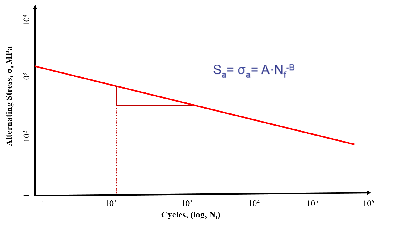
- Fatigue life is based on Wholers curve (alternating stress range and SN curve).
- Goodmon, Gerber, soderberg, ASME Elliptical mean stress correction theories are used.
The S-N curve is commonly used to estimate the degree of fatigue damage to materials. This curve is also called the Wholer curve, which is the oldest diagram which allows one to visualize the resistance of the part or the materials in the field of fatigue. This curve defines a relation between the applied stress σ ( sigma sometimes noted S) and the number of cycles to failure. Mathematical description of the material S-N curve is shown in figure 4.
Strain-Life Method:
Strain Life method is also known as local stress-strain, critical location approach, E-N or crack initiation which uses plastic strain to predict the fatigue damage. It is commonly referred to as the low-cycle-fatigue (LCF) method but it can also be used in the high cycle (HCF) domain. In the presence of stress concentration, when strain is no longer elastic, the total stain can be used instead of stress to predict fatigue life, this is known as strain life method.
Strain-life design method is based on the assumption that the behavior (fatigue life) of notched part at a notch root is similar to small test specimen under strain controlled conditions. Figure 5 shows components under pull force along with small test specimen. Here, the overall body remains elastic while the localized plasticity (critical zone) can be simulated using smooth test specimens.
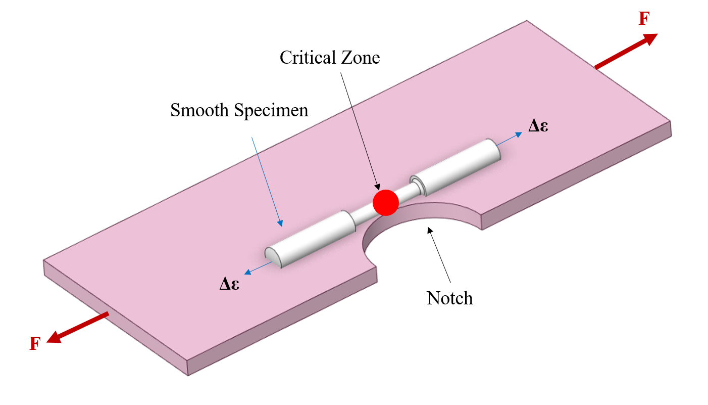
When strains are no longer elastic, such as in the presence of stress concentrations, the total strain can be used instead of stress as a similitude parameter. This is known as the strain-life method.
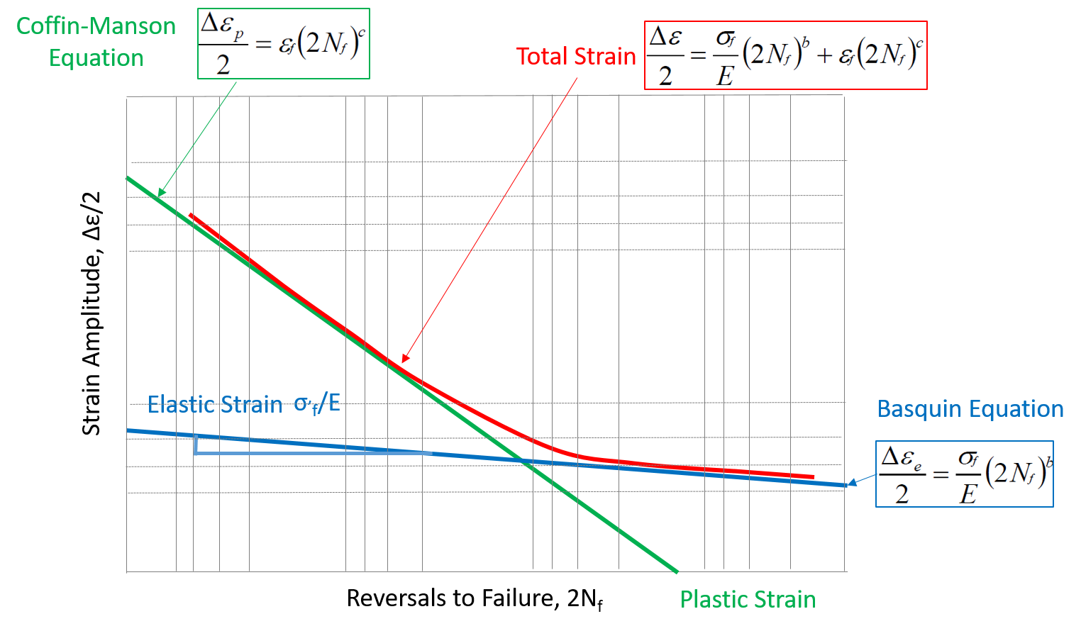
The figure 6 shows the strain amplitude vs reversal of failures (2Nf). The total strain is obtained from the equation shown in figure.
Key features of Strain-Life methods:
- It uses elastic-plastic strains estimated from elastic results or even calculated directly.
- Best suited for low cycle fatigue and can be used for high cycle fatigue too.
- It is difficult to apply with hand calculations hence generally implemented using numerical methods like CAE.
- Rainflow cycle counting can be used to simplify the complex fatigue cycle loads.
- Predicts crack initiation and stress amplitude of local strain at the crack initiation phase
Vibration Fatigue (Frequency Based Fatigue):
As we know, fatigue is the initiation and propagation of cracks in a material due to cyclic loading. These cyclic loads may happen in vibrations too, due to its own natural frequency or other external excitation such as random vibration, harmonic vibrations, etc. This forced vibrations of random or harmonic natures causes material fatigue, called vibration fatigue. The structure responds to its natural dynamic modes due applied excitations, resulting in dynamic stress in the material points. The process of vibration fatigue is thus governed largely by the shape of the excitation profile analyzed in frequency domain, power spectral density (PSD).
The vibration fatigue analysis is mainly based on the modal analysis response as natural modes and frequencies of vibrating structure which enables accurate prediction of the local stress responses for the given excitation. Thus, when stress responses are known, the vibration fatigue is said to be successfully characterized.
There are few classical approaches which are used to calculate the fatigue evaluation; in this rainflow algorithm is used to simplify cycle counting & palmgren miner damage hypothesis is used to sum damages of respective cycles. In combination with classical approaches, FEM is being used nowadays to calculate fatigue damage. FEM performs the frequency domain dynamic analysis for given fatigue loads. There are various commercial software which provides frequency based fatigue calculations such as ANSYS Fatigue, Ncode, Abaqus, Nastran, etc. ANSYS mechanical fatigue tool supports fatigue analysis for random vibration and harmonic response analysis.
Applications:
- Automobiles traveling on roadway
- The wind blowing on the wind turbine
- Waves hitting offshore structures and marine vessels
- Space vehicles during launch
Crack Growth Methods:
In this method, the fatigue life is estimated based on the developed crack growth for each loading cycle; the crack growth equations are used to sum the width of each increment of crack. Paris Erdogan equations are used to predict the fatigue life of components which are useful to predict the growth of crack from 10 micro M to failure. The ASTM international has developed standard methods for measuring crack growth.
The crack growth methods predict the intermediate size of cracks which are used to schedule inspections to ensure safety of components whereas strain life/stress life only give life until component fails. FEM software’s also used to predict crack growth through fracture mechanics parameters.
Furthermore, refer fatigue Design philosophy blogpost for more insights on fatigue analysis.
Summary
- Fatigue is the Initiation, formation and propagation of cracks in a material due to cyclic loads.
- There are three stages of fatigue fracture: Crack initiation, Crack propagation and Final rupture.
- There are two major methods to predict fatigue life the first one is stress (S-N) life and second one is Strain (E-N) life. In addition to this, frequency based or vibration fatigue & crack growth (crack-life) methods are used to predict fatigue life.
One comment
Comments are closed.