
As we know fatigue is very important term in engineering and which if not studied will leads to failure of structure and causes fatal accident. Hence, design In this blog, we will going to discuss about the design philosophy of fatigue. Before understanding design philosophy you should aware of What is fatigue and its various stages.
Fatigue Design Philosophies:
There are three primary design philosophies used with respect to fatigue and durability of structure. These are Safe Life, Fail Safe and Damage Tolerance. These design philosophies are used even before attempting to carry out fatigue calculations or even before deciding the calculation method of fatigue. These design philosophies are mainly used in aerospace industries such as aircraft & helicopter structure. This fatigue design philosophies methods are also used other industries such as automotive, industrial products, static equipment’s, the practical examples are discussed below:
The safe-life approach is used for planning and envisaging the toughness of the mechanisms in the automotive industry,
The fail safe design in Roller-shutter fire doors that are activated by building alarm systems or local smoke detectors must close automatically when signaled regardless of power,
Isolation valves, and control valves, that are used for example in systems containing hazardous substances, can be designed to close upon loss of power, for example by spring force. This is known as fail-closed upon loss of power.
Safe Life:
In the safe life design approach, the products are designed to survive specific design life, meaning products are intended to be removed from service at a specific design life. This method is used in critical systems components whose failure may cause severe damage to life and which are very difficult to repair and hence these systems are designed to work for years without any repairs.
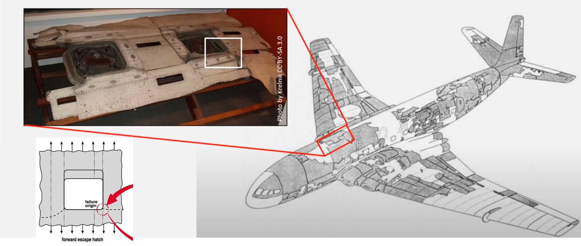
As the components were designed to perform for intended design life, this may also lead to huge disadvantages of the system. In order to satisfy this design philosophy, serious assumptions were made about alternating loads regardless of whether it will perform for design life or not and if cracks were introduced due to alternating loads before their service life, it may lead to huge accidents of the whole system. For example, De havilland comet accident (1950): During the comet era, the aircraft design used was predominantly using Safe-Life approach, which means the aircraft structure was designed to sustain the required fatigue life with no initial damage or crack and no accumulation of damage during service. But the Comet accidents showed that around stress concentration cracks would initiate and propagate much earlier than expected, such that safety could not be universally guaranteed in the SAFE-LIFE approach without uneconomically short aircraft. Refer figure 1 showing failure origin of comet G-ALYU around window.
To counter this disadvantage, alternative design philosophies like fail-safe design and fault-tolerant design were developed.
Fail- Safe Approach:
Fail safe approach is a design feature which incorporates various techniques in the event of failure to mitigate the losses so that the failure will cause minimal or no harm to the equipment, environment or people. The system design with a fail safe approach does not mean that the failure will not happen, but rather than the system design mitigates the unsafe consequences of the system failure, meaning if the system fails, it will fail in a safe manner.
In case of aircraft design, Fail-safe is the characteristics of the structure that permits it to retain required residual strength for a period of un-repaired use after failure or partial failure of a principal structural element. The design principle emphasis on using multiple load paths means multiple elements carrying the loads. This approach developed in 1950, limited service life of critical components, failure of primary members does not risk safety of aircraft because other components still carry the loads resulting in a more robust design of the structure. The issue with this approach is that it does not anticipate all failure modes & it is ineffective in multiple site damage.
Examples:
- The control valves and isolation valves that are used for example in systems containing hazardous substances are closed by spring force when loss of power may happen. This is known as fail-closed upon loss of power.
- A railway semaphore signal is specially designed so that, should the cable controlling the signal break, the arm returns to the “danger” position, preventing any trains passing the inoperative signal.
- Many nuclear reactor designs have neutron absorbing control rods suspended by electromagnets. If the power fails, they drop under gravity into the core and shut down the chain reaction in seconds by absorbing the neutrons needed for fission to continue.
Damage Tolerance:
Damage Tolerance is the ability of the structure to resist failure due to presence of defects, cracks, or other damage for a time period sufficient to enable their detection. This approach is based on the assumption that the flaws can exist in any structure and such flaws can propagate with their uses.
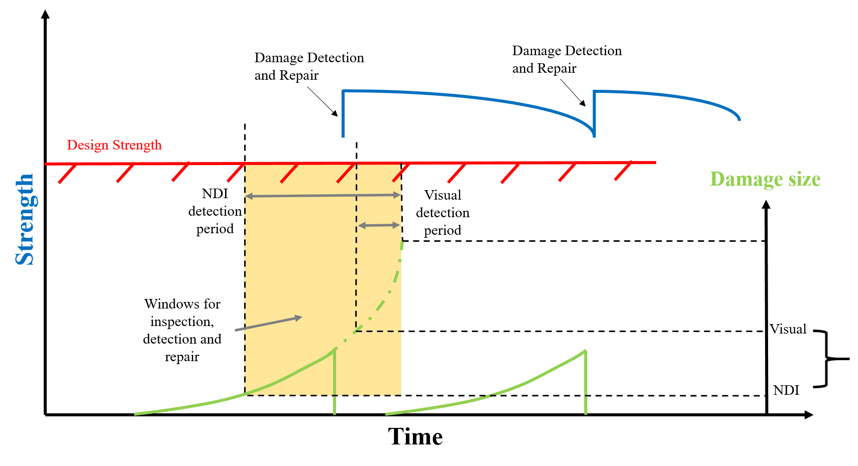
Damage tolerance, or safety by inspection, was developed as a design philosophy in the 1970s as an improvement on the fail-safe principle for structural deterioration.it is also called as ability of the structure to sustain anticipated loads in the presence of fatigue, corrosion or accidental damage until such damage is detected through inspections or malfunctions and is repaired. This philosophy is based on repairs performed on defective structures should restore its original strength. Although damage tolerance philosophy increases the durability of the structure, it does not guarantee safety of airframe. This is illustrated by the accident of aloha airlines, in which the Boeing 737 lost a significant portion of upper fuselage structure and the cause of accident was due to multiple site damage in riveted joints. These joints are insufficiently inspected which are susceptible to corrosion. Figure 2 shows the lifecycle of damage tolerance, the graph shows that once the damage is detected by NDI and visually, it partially repaired and its its initial strength is achieved time to time period.
One comment
Comments are closed.