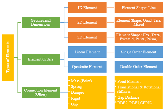
There are different types of finite elements. These are mainly classified based on geometrical dimensions (1D, 2D & 3D), you can further add types based on element order, other or miscellaneous types. Refer Figure 1 for types of elements:
Figure 1: Types of FEA Elements
1.Geometrical Dimension:
1D Element:
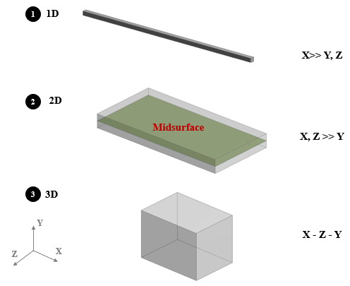
In case of 1D elements one of the dimensions is very large compare to other two dimensions. For example pipe, rod, bar, beams, axisymmetric shell etc. In all this examples the length of the element is quite larger compare to width, height, or diameter. Refer Figure 2, 1st image shows 1D rectangular beam, in which length is very larger compare to height and width.
Modeling: The shape of 1D element is line which is created by joining two nodes. So the length is defined by modeling line while other dimension are defined by assigning respective cross sections to the line. Likewise 1D element is modeled in FEA. FEA software codes includes many standard cross sections such as C Channel, I beam, rectangular, square, circular & hollow section and even user defined section too.
Practical Examples: Long shafts, pin joints, connection elements, etc.
Advantages:
Solution computing is faster: Only one element across cross section compare to 2D and 3D elements, results significant reduction in mesh count & solution time.
Less efforts for modeling and meshing
Design changes are easier: Just need to change the cross section of the (beam elements)
Fruitful for automation and design codes: There are lot of codes and design guidelines guides on beam design
2D Element:
In case of 2D, two dimensions are very large comparison with third one. For Examples, plane stress, plane strain, axisymmetric solid, thin shell, plate, membrane, etc. Refer Figure 2, 2nd sketch shows 2D plate in which width & length are very large compare to thickness.
Modeling: 2D shapes are plate structure for which midsurface is extracted and thickness is assigned on both the side of the surface (half thickness on either sides). Moreover, sometimes top and bottom surface are extracted and respective thickness is assigned (For top surface bottom side while for bottom surface top side thickness is assigned so that exact geometry shape is represented). Quad, Tria, Rtria are the primarily element shapes used to define the 2D elements.
Practical Example: Thin vessels, sheet metal parts, plastic components like instrumental panels, etc. Generally 2D meshing is used when width to thickness ratio is greater than 20.
The Pitfalls:
Advantages like 1D elements in terms of less modeling efforts and faster simulation compare to 3D Elements.
Have limitation when irregular surface with different features on two sides.
Difficulties to see stresses across thickness like in case of stress linearization approach for pressure vessels.
3D Element:
In case of 3D, all dimensions are comparable for example solids. Refer Figure 2, 3rd sketch shows the cube in which all the dimensions like length, width & height are comparable with each other. .
Modeling: Tetra, Penta, Hex, Pyramid are the primarily element shape used to define the 3D elements. If geometry is sweepable or mappble (for example shell in case of vessel) then Hex mesh is preferred or else tetra mesh is used. For all irregular shapes tetra mesh is used. If the structure is having sweepable as well as irregular shapes in such scenario the combination of hex, tetra and pyramid or penta in between is used.
Practical Examples: Industrial valves, Casing, engine block, connecting rods, etc (most of real life objects are solids).
Figure 2: 1D, 2D , 3D Elements
2. Element Order
Linear (Single Order) and Quadratic (Double Order) Elements:
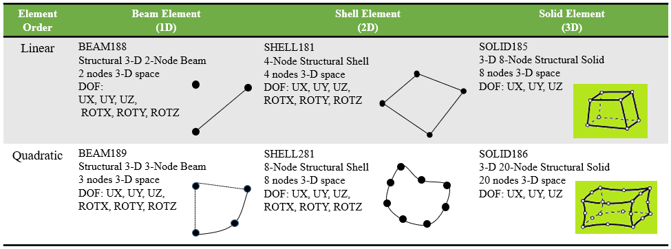
As we discussed the major element types are 1D, 2D and 3D and all these elements are further segregated based on mid-side nodes availability. The only difference between linear and quadratic is midside nodes. In case of quadratic element, additional midside node in is defined in middle of each side. Quadratic elements (higher order elements) are benefits of higher degree of accuracy per element, greater geometry capture. But it also increases node count and then results in higher computation time. Generally higher order elements are most often used in 3-D solid modeling because the potential to reduce modeling effort and the number of elements required to capture the geometry is greater. While first order or linear element does not have midside nodes & hence are preferable in case of lower mesh count and faster solution response (for example explicit simulation uses first order elements). Refer Table 1 for first order and second order elements.
3.Connection (Other) Elements:
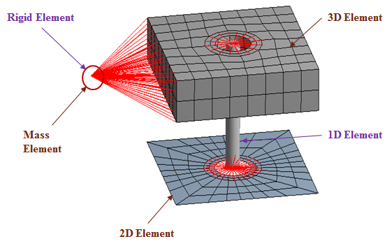
This are the elements which not primarily used to capture the geometry but to define the connections, mass elements, etc. Sometime we did not modeled all the component in the FEA, in such cases, those component does not considered in the model (like mounting components or accessories) are defined with point mass or mass elements (It can be defined at CG location and respective component mass along with inertia in each direction is defined). Furthermore rigid elements like RBE2, RBE3, CERIEG are used to define connection between two components, etc. Spring and damper are used to define actual spring with stiffness values.
Figure 3: Types of Element in ANSYS
Element Types Based on Element Names:
There are various FEA software’s available in the market and for each element type you will find different element name and algorithms. Table 1 shows the linear and quadratic elements types for beam, shell and solid element from ANSYS software. Likewise if you are using other software like Abaqus, Radioss, Nastran, etc, you will find different names for the respective elements.
Table 1: Element Name & Types ANSYS
Selection of Element Type:
As we discussed the types of elements but do you know How to decide element types? There are few parameters which decides the selection of element type.
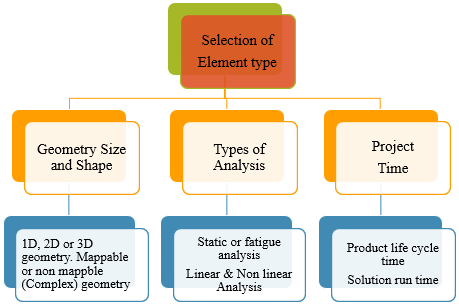
Figure 4: Selection of Elements Type
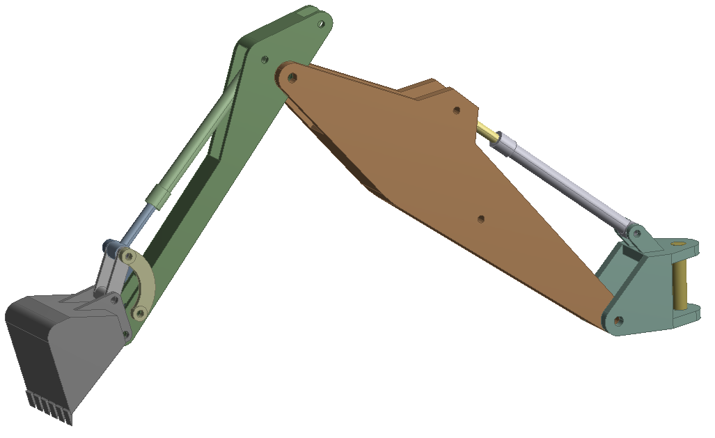
First Category important category is geometry size and shape. As discussed above, the longer shape like beam or pipe is modeled with 1D elements while planer geometry is modelled with shell elements and thick and complex geometry is modelled with solid elements. The Figure 5 shows the practical example for excavator, here the cylinder can be modelled with 1D and the frames (having plate structure) with 2D shell elements while the bucket ( having irregular geometry) can be modelled with 3D solid (tetra) elements. The choice is yours, As FEA analyst this is challenging task but after years of experience and knowledge of each element formulation, you can easily decide the selection of elements based size and shape.
Figure 5: Excavator FEA Modeling Approach
Second Category, is types of analysis, here if you are simulating explicit dynamic simulation like impact or drop then you might need to go with first order elements. Nonlinear material simulation (like hyperelastic materials) are preferred to model with second order elements. Static and fatigue analysis quad and hex elements are preferred over trias, tetras, etc. In case of mold flow analysis triangular elements are preferred over quadrilateral.
Third Category of element type selection is project time, here based on project time you need to choose the types of elements and faster method of meshing. Meshing for critical components is time taking process and hence if you have time limitation, then you will prefer to go with auto mesh, batch mesh options, faster generating elements like tetra over hex. Also 1D or shell elements are preferred over solid elements because solid mesh method create more nodes and result higher solution time.
References:
Practical Aspects of Finite Element Simulation A Study Guide, Altair University.
ANSYS Element Library
3 comments
Hi ,
Recently i have done some of the analysis in Ansysand I got some error while doing so, as shown below;
1) Material number 3651 (used bt element 942947) should normally have at least one MP or one TB type command associated with it.Output of energy by material may not be available.
2) Real constant set 1 undefined but referenced by element 1.
could you pls. show the solution for these above mentioned problems.
thanks in advance
Dinesh G
Hello Dinesh,
1. This error is related to material. Please kindly check material definition (some material properties might be missing) and assigned to respective elements.
2. It is further related to real constant, please check properly you have defined and assigned to respective geometry or not.
Bothe errors are related to your problems and can be resolved based on understanding your problem correctly.
Thank you very much for your support!
how can I share the screen shots or the model picture with you?
thanks
Dinesh G