
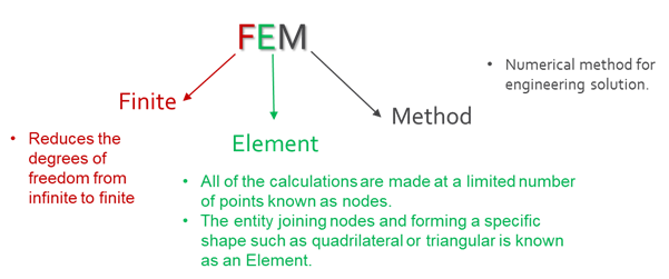
The finite element method (FEM) is the most widely used method for solving problems of engineering and mathematical models. It is based on matrix algebra to solve systems of simultaneous equations, partial differential equations and hence it is also called as matrix methods of structural analysis. It is a computer based tool which has been developed and used long before for simulating and analyzing engineering products and systems.
With the finite element method, a continuous system is idealized by a discrete system or smaller parts called the mesh. Meshing is a preprocessing technique which divides the system or body in an equivalent system of finite elements, interconnected at a finite number of points on each element called Nodes. This whole process of dividing continuous objects into discrete parts called as Discretization.
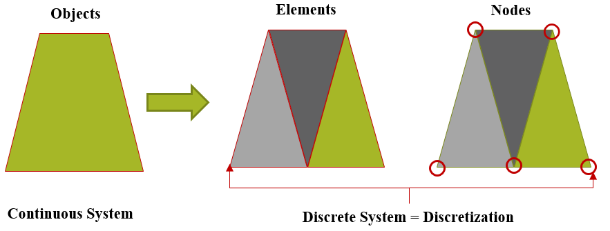 Thus, discretization is used to make problems solvable for computer by converting structural problem with infinite number of degrees of freedom (continuous system governed by Partial Differential Equations) into problem with a finite number of degrees of freedom.
Typical problem areas of interest include the traditional fields of structural analysis, heat transfer, fluid flow, mass transport, and electromagnetic potential, Ship Building, packaging, etc.
Why Do Finite Element Analysis?
To solve any engineering problems analytical, experimental and numerical methods are used. Both analytical and experimental methods have larger limitations and will be used for simpler problems. But when problem involves more complexity in the form of complex geometry, multi supports, various loading events & different material properties the analytical and experimental method is not useful. In such scenario, the Numerical methods like FEM are most widely used.
The most common advantages include:
- Reduction of design & development time
- Optimized product performance and cost
- Elimination or reduction of testing
- Improved safety with desired factor of safety
- Satisfaction of design codes by following validation in accordance with universal design codes.
- Fuller understanding of components allowing more rational design
- Satisfaction of legal and contractual requirements.
- Visualization of object insights (Inside product behavior for applied loading)
Basic FEA Terminology:
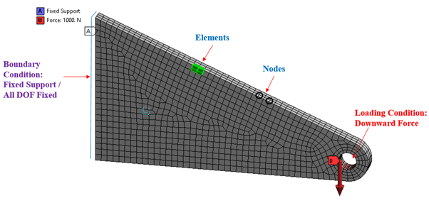
Any FEA system is represented by a discrete system of any input geometry like element, nodes, loading & boundary conditions. Refer Figure 1, which shows FEA model of triangular bracket with downward force acting in the center of hole. Such system (analysis deck) is an input for any solver (simulation softwares), which gives results at each and every nodes after successful completion of solution.
How Does FEA Work Process Flow Works?
The very first step in FEA is to understand the inputs, geometry to be analyzed. Once clear understanding on inputs like drawings, materials, loading are identified, the next step is to create the computer model of the input geometry by segmenting into individual elements with basic shapes like square and tria for shell and cubes for solid elements. Then, material properties are assigned to each element with respective loading conditions like forces, moments, pressure, etc. and fixing locations are defined. Once a complete FEA deck is ready the next steps will be the solution, where software codes use various mathematical equations (stiffness, force and displacement matrix formulation) to predict the behavior of each element. Furthermore, computational methods and various failure theories are used to combine the responses, which is used to predict the overall behavior of the analyzed part. The FEA method permits the analyst to compute the stiffness and strength of the analyzed structure during and after the simulation, allowing the visualization of the displacements and the distribution of the stresses and strains inside the structure. Refer Figure 2 showing flow chart for FEA workflow.
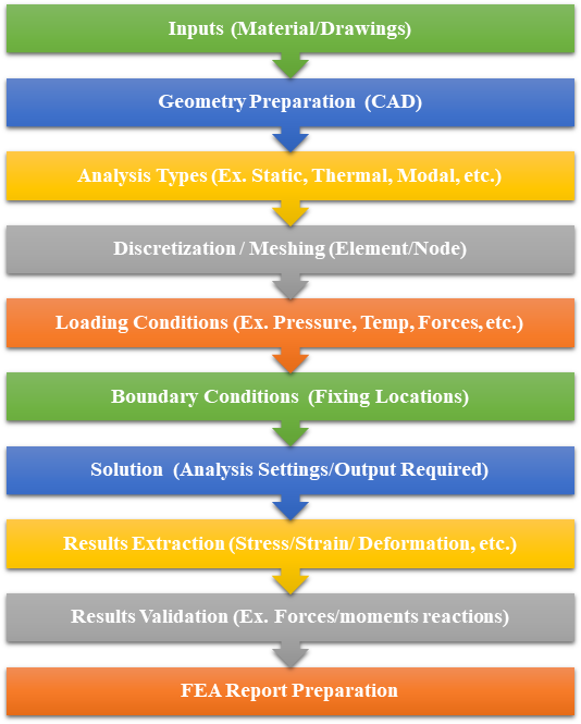
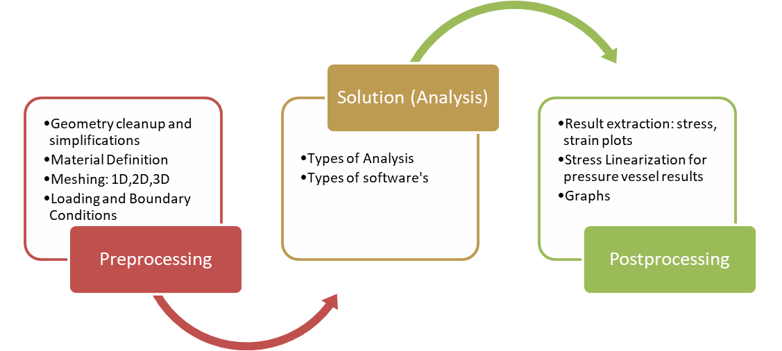
Furthermore, FEA process flow is mainly divided into three phase: First phase is Pre-processing where all the geometry cleanup and complete FEA model creation work involves while second phase is Solution where the analysis setting, results output definition, etc are key parameters: the last and important phase is Post-processing, which involves results extraction, results validation and final report preparation. Refer Figure 3 for FEA process flow.
Refer below Video for Basics and Practical Introduction of FEA
Thank You