
Pressure vessel consist various components such as nozzle, shell, head, supports, skid & other accessories. Also these vessel have various input, output and intermediate connections as per functionality with other components through nozzles. These nozzle connections experienced internal as well as external loads (piping loads) during various loading events.
If you looking to analyze any particular connections (nozzle) of the pressure vessel, then it not worthy to consider the whole vessel, as it will consume more time for modeling, meshing & for the solution. And hence most of vessel engineers prefer to consider only respective connection and nearby region instead of whole vessel. Here, only region of interest of the vessel is considered, all other remaining part is sliced and suppress for the simulations. By doing so we reduced the efforts but at the same time we create the openings at the cut boundaries i.e. at sliced region of the vessel shell. In such case, when the internal pressure acts on the vessel, the vessel will not be in equilibrium state as internal pressure cause it to move radially outwards at this cut boundaries or openings (at sliced region). And hence to make the system in equilibrium equal and opposite force is applied at the opening which is called as pressure thrust or compensating force. It is equal to internal area into internal pressure. (CF = -Pi*Ai)
Furthermore, another way to compensate the effect of internal pressure at the openings, thrust pressure is applied at the outer area of the opening is called as compensating pressure. It is calculated analytically by equating force developed at openings. While applying in FEA its direction is consider negative so that it can compensate the internal pressure effect.
Refer below calculations,
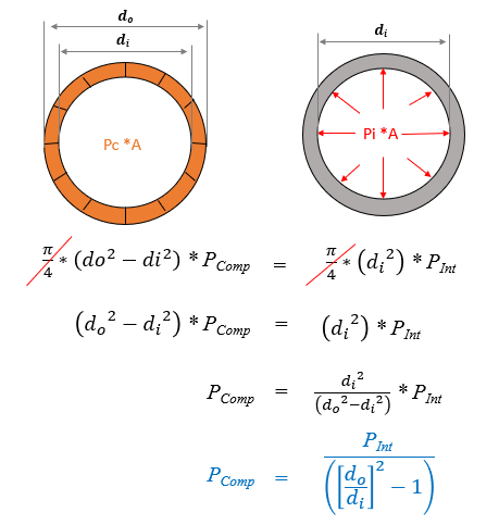
Compensating Force or Compensating Pressure?
When we apply remote force there might be chances of localize stress developed at the remote connection and hence compensating pressure can be consider over compensating force. When you apply compensating pressure at one end of the shell opening and other end is fixed, you will get reaction (at fixed location) which is same as compensating force.
Still you might came across few more questions, such as:
- If we are analyzing any single nozzle from complete vessel, then up to what extent we should consider shell length?
- Should we apply compensating pressure on one end or both end (Nozzle is at the middle of the vessel) ?
- Can we apply CP at all other openings like nozzle ends?
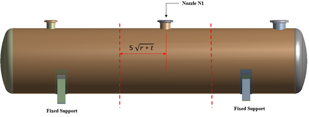
Regarding up to what region we should consider shell length; there is no specific criteria, it depends on engineers judgments and effect of openings on the analysis. To properly capture the membrane behavior, 5 times square root of internal radius into thickness distance is used. Suppose if you are analyzing nozzle which is middle of the shell then you can use 5 sqrt(r*t) distance on either sides from center axis.
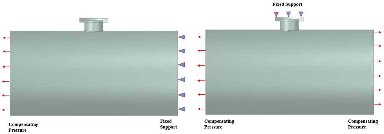
Regarding should we apply compensating pressure on one end or both end; If the nozzle is at the middle of the vessel and considered some regions of the shell on either side for simulation, then you can apply at any one end and keep constrain at other end. This is due to the fact that FEA will not solve until few constrains are not provided. If you are applying constrain on nozzle top flange, in that case you can apply compensating pressure on both ends of the vessel. Figure 1 shows shell end conditions for the analysis, the first condition shows one and fix and other end CP (here you also need to apply CP on Nozzle face), while second condition fixed support is applied on flange and CP are applied on both sides of the shell.
Regarding can we apply CP at all other openings like nozzle ends: Yes you can consider the compensating pressure at nozzle or all other openings. You just need to calculate the CP, based on your areas of openings as mentioned in above.
We will further discuss this terms through one below example;
Analyze the nozzle N1 of horizontal vessel (Refer Figure 2) for internal pressure loads (1.5 MPa). First calculate, the compensating force (1.7135E+06 N) and compensating pressure (-37.3162 MPa).
Here, the global model of the horizontal vessel is compared with local model of nozzle N1 with different boundary conditions (shell end conditions) and comparative study is presented below:
- Global Model (Horizontal pressure vessel)
- Nozzle N1 Model (One end fix and other end is compensating pressure, CP)
- Nozzle N1 Model (One end fix and other end is compensating force, CF)
- Nozzle N1 Model (Both end fix)
Conclusion:
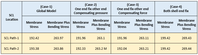
Table 1 presents the membrane and membrane plus bending stress comparison for global and local (nozzle N1) model. The global model (Case -1) results are closure to case 2 (one end fix and other end is applied with CP) & case 3 results (one end fix and other end is applied with CF). The results for case 4 are more conservative compare to case 2 & case 3.
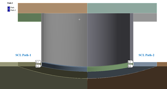
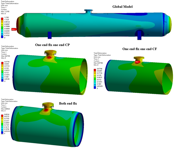
When we provide all degrees of freedom constraints at shell both ends, it does not allow the shell to deform, it completely lock the shell movements at ends. That’s why we found higher stresses in this particular case, while in case of compensating pressure/force case, it only compensate thrust effect it does not lock the shell movements. You can check the deformation plots as shown in Figure 4. Here you can easily identify the shell end behavior with respect to end conditions.
You might have understood the concept of Compensating pressure. When you are locally analyzing any nozzle shell connections, you can either fix the shell ends which is worst case condition or else you can fix one end and apply compensating pressure at other ends to get more realistic results closure to global model.
I am interested