
APDL stands for ANSYS Parametric Design language which simulates various types of analysis such as Structural, Acoustic, Thermal, Piezoelectric, Electromagnetic, etc.
- APDL uses powerful scripting language to represent each model and analysis types.
- APDL offers various conveniences such as macros, looping, table & array, parameterization, branching and complex math operations, etc.
- APDL is base for various features which are not even exposed to workbench mechanical and hence sometimes we need to use APDL scripting in mechanical.
If you know the APDL script language then even more complex simulation will become easier. APDL also have GUI where you can prepare the FEA deck and perform the analysis by selecting various options from main GUI menu. The GUI creates APDL commands and sends them to MAPDL, which processes the commands continuously as they are received. In this blog we will discuss about How to perform the cantilever beam analysis through MAPDL ? We will discuss how to create APDL script for geometry creation, material assignment, meshing to results extraction through MAPDL. APDL also called as Mechanical APDL (MAPDL) or ANSYS Classic.
Cantilever Beam Analysis through APDL:
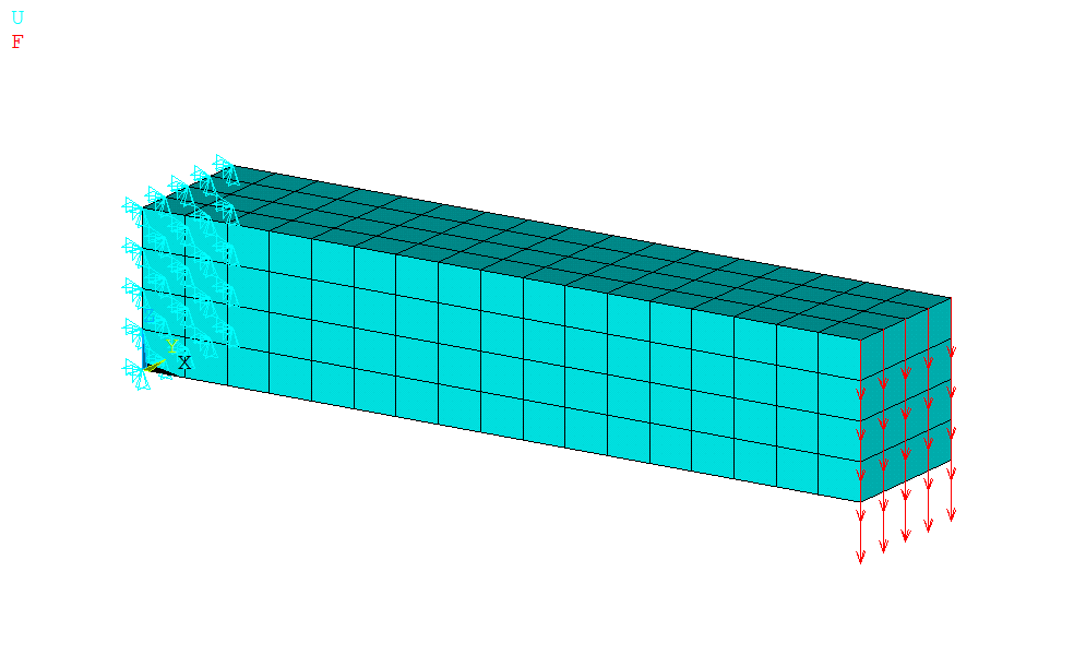
Perform static structural finite element analysis of cantilever beam as shown in figure 1. Right hand side of the beam is applied with force of 25 KN while left hand side is fixed in all degrees of freedom. The beam dimensions for length, width & height are 100 mm, 20 mm & 20 mm respectively. Use structural steel properties for material details.
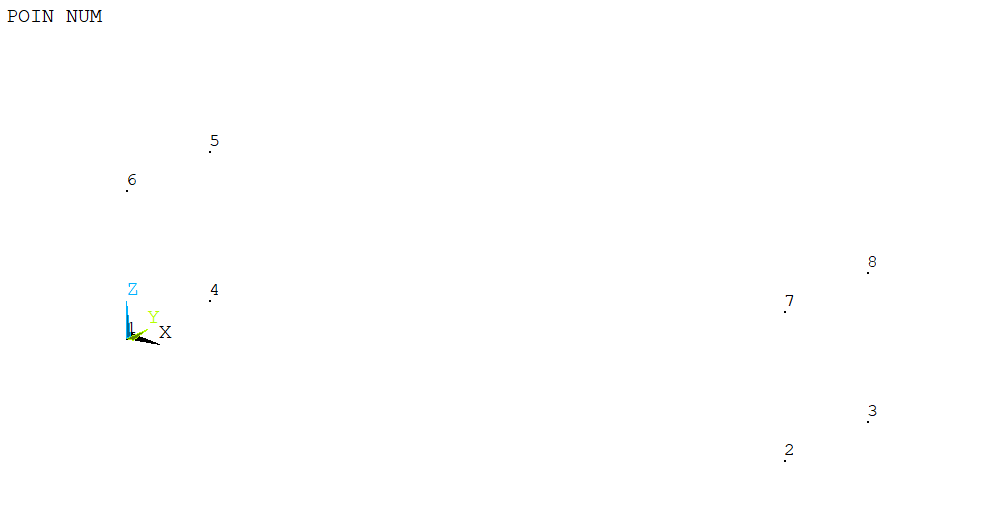
1. Keypoint Modeling
Create keypoints as per respective x, y & z coordinates.
/PREP7 ……………… ! Start Preprocessor
K,1,0,0,0
K,2,100,0,0
K,3,100,20,0
K,4,0,20,0
K,5,0,20,20
K,6,0,0,20
K,7,100,0,20
K,8,100,20,20
2. Lines Creation:
Create straight line from keypoints.
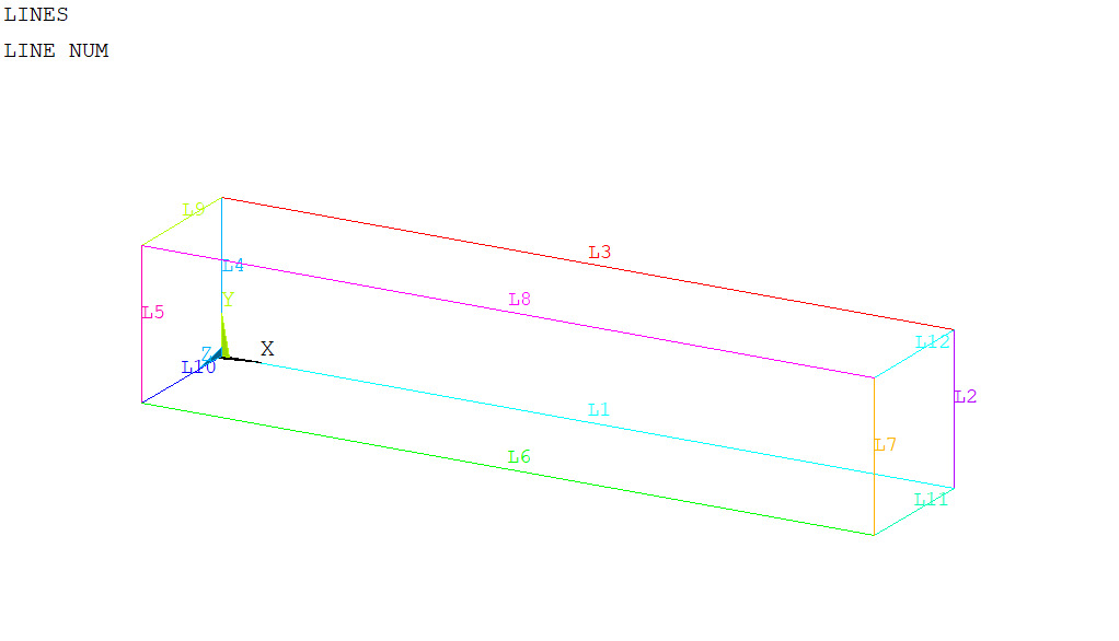
LSTR, 1, 2
LSTR, 2, 3
LSTR, 3, 4
LSTR, 4, 1
LSTR, 5, 6
LSTR, 6, 7
LSTR, 7, 8
LSTR, 8, 5
LSTR, 4, 5
LSTR, 1, 6
LSTR, 2, 7
LSTR, 3, 8
3. Area Creation
Create area from lines.
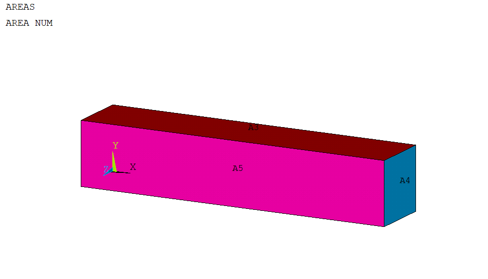
AL,1,2,3,4
AL,4,9,5,10
AL,3,9,8,12
AL,2,12,7,11
AL,6,7,8,5
AL,1,11,6,10
4. Volume Creation
Create Volume from areas
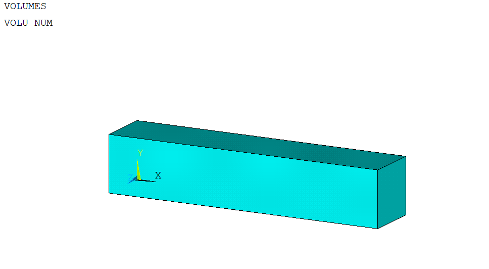
VA,1,2,3,4,5,6
5. Define Element type:
Use solid element for solid structure modeling. SOLID185 is used for 3-D modeling of solid structures which is defined by eight nodes having 3 degrees of freedom at each node (translations in the nodal x, y & Z directions)
ET,2, SOLID185
6. Define Material Type:
Define linear elastic isotropic material. Define steel Young’s modulus and Poisson ratio.
MPTEMP,,,,,,,,
MPTEMP,1,0
MPDATA,EX,1,,210e3
MPDATA,PRXY,1,,.3
7. Perform Meshing:
Perform volume meshing with sweep option and used 6 element size.
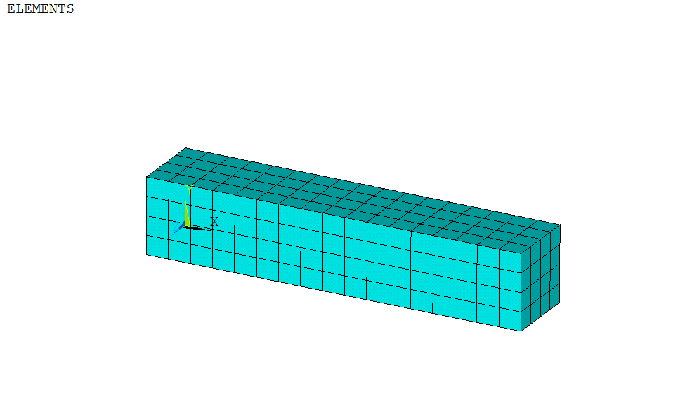
ESIZE,6,0,
VSWEEP,ALL
Create Components
Create components for applying loading and boundary conditions in the model. Create components for force face & fixed support face.
ASEL,R,,,4 (! Select right side area)
CM,Force,AREA (! Create area component)
CMSEL,A,Force
ALLS
APLOT
ASEL,R,,,2 (! Select left side area)
CM,FIXED_SUPPORT,AREA (! Create area component)
CMSEL,A,FIXED_SUPPORT
ALLS
APLOT
Apply Loading and Boundary Conditions:
Apply force and fixed on components created above. Force area component will transfer loads from area to nodes (lied in the area face). Divide total force per nodes. For 25 KN and 25 nodes, apply force of 1 KN on the face.
/SOL
ANTYPE,0 ( ! Define solution type static)
D,FIXED_SUPPORT,ALL
F,FORCE,FZ,-1000
Solution:
Solve the solution
/SOLU (! Enter in solution tab)
/STATUS,SOLU
SOLVE
Result Extraction:
Extract the total deformation and equivalent stresses
Total Deformation
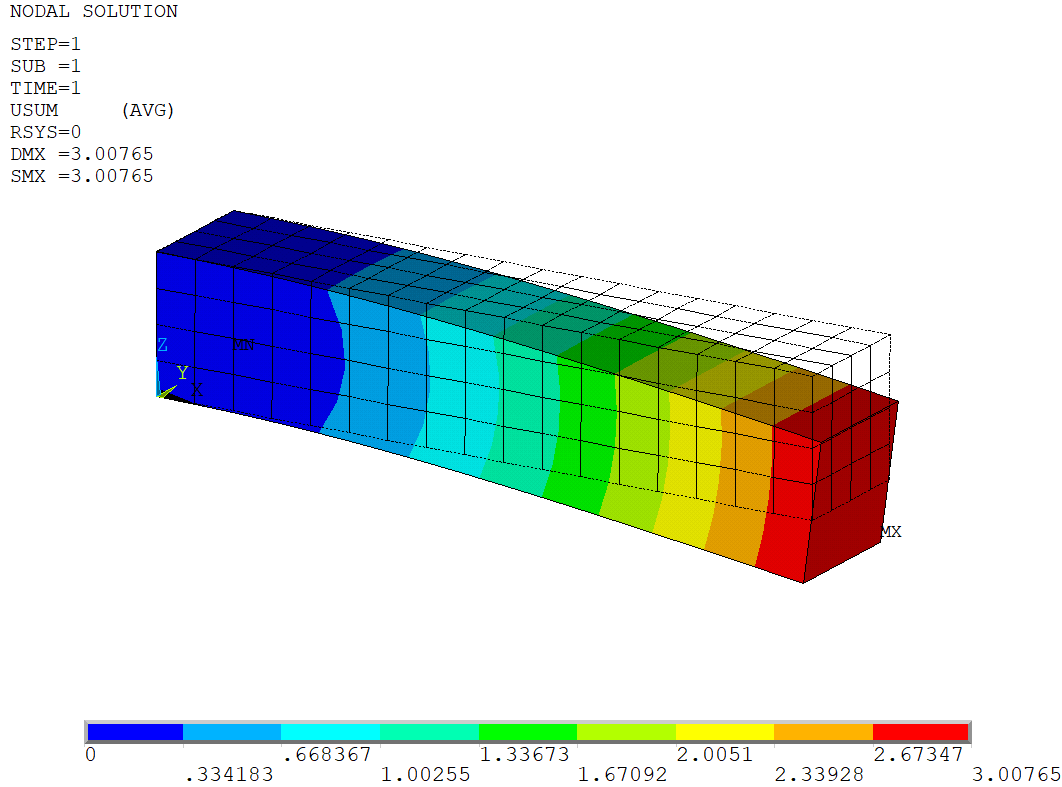
/POST1 (! Enter in General postprocessing )
/EFACET,1
PLNSOL, U,SUM, 0,1.0 ( ! Plot total deformation)
PLNSOL, U,Z, 0,1.0 (! Plot directional deformation in Z axis) /DSCALE,ALL,3 ( ! Create Scale plot @3)
/EFACET,1
PLNSOL, U,SUM, 1,1.0
Equivalent Stresses:
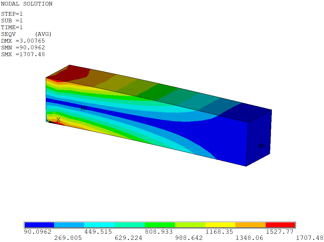
/DSCALE,ALL,1.0 (! Select true scale)
/EFACET,1
PLNSOL, S,EQV, 0,1.0 ( ! Create equivalent stress plot)
Results Animation
PLNSOL,U,SUM (! Total Deformation plot)
ANCNTR,10,3 (! Create Animation @scale 3 for 10 frame)
Reaction Extraction:
Extract the force reaction and match with the applied force. If the applied force is matching with reactions force means FEA is correct.
PRRSOL, (! Reaction in X, Y & Z direction)
PRRSOL,FZ ( ! Reaction in Z direction)
! VALUE 0.12173E-007 -0.26439E-007 25000.
Summary:
This blog present how to perform the cantilever beam FE analysis using APDL commands through various FEA steps such geometry creation, meshing, material assignment, meshing, loading and boundary conditions and results extraction & validation.
Similar process is used to perform any complex simulation using APDL.
what could be reason for not having the reactions (moment or forces ) matching with the applied forces?
could you pls. explain it for workbench with an example?
Reactions are matching with the applied forces. The Applied force is 25000 N and check Z direction reaction from FEA is same as applied force.
is the bonding play any role in this?(contacts)
There is no contact. It is single body only.