The ASME Boiler & Pressure Vessel Code (BPVC) is an American Society of Mechanical Engineers (ASME) standard that regulates the design and construction of boilers and pressure vessels. These are real world working standards developed for safety of vessels which were developed long time ago after several accidents and causalities were happened. It is common pool for every vessel designers as well as manufacturer across the world. As time passes, the vessel no longer simpler but the complexity in terms of size & shape, welding connections, materials are being observed.
Furthermore, stress assessment thorough finite element analysis tool are developed and being used which allows to see stresses inside the vessel components. Nowadays, Finite element analysis is no longer a magical tool which were used earlier only in research labs.
Many industries have developed FEA software’s which are being used for design validations & optimizations. Though the vessel calculations are performed with FEA software’s, but analyzing the stresses found in the pressure vessel is still difficult task. It needs skills to identify high stress locations and justify the results, furthermore the pressure vessel validation is performed with respect to ASME guidelines. FEA tools gives different types of stresses in vessel which have different safety implications.
This blog article explains, how the stress linearization tool works to separate various stresses like membrane, bending & peak.
Stress classification Line:
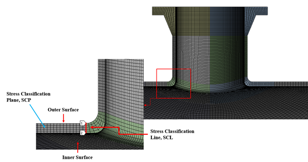
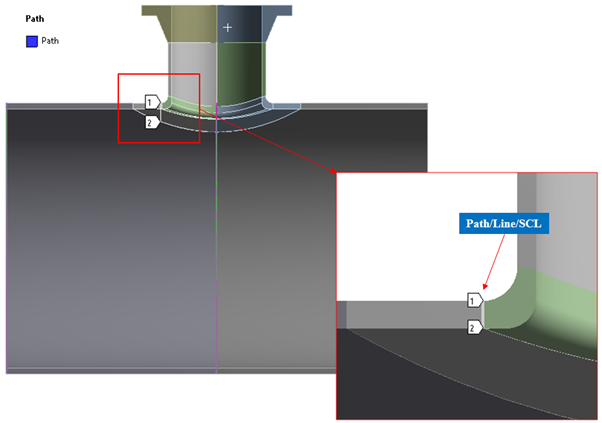
A Stress Classification Line or SCL is a straight line running from the inside to outside of a vessel. It is perpendicular to both inside and outside surfaces of the vessel. In FEA, stresses are calculated at nodal points and SCL is passing through these nodes. Thus, SCL tool takes stresses at each and every point along path and segregates into different stress components like, membrane stress, bending stress, membrane plus bending, peak and total stresses. These membrane and bending stresses are developed on cross sections through the thickness of a component. These sections are called stress classification planes (SCPs). SCPs are flat planes that cut through a section of a component. Figure 1 presents the SCL & SCP on nozzle shell junction component.
Figure 1: Stress Classification Line & Stress Classification Plane
Membrane Stress: Membrane stresses are nothing but average stress across the thickness. Membrane stresses are always positive and it is difficult to predict whether they are positive or negative as magnitude are provided but directions are missing.
Bending Stress: Bending stress is the linearly varying stress through the thickness, which is difference in stresses from inside to outside surface.
Membrane + Bending: As name suggest, these stresses are sum of membrane and bending stresses.
Peak stress: These stresses arehighest stress found along the SCL. This is also always positive but not necessarily higher than the membrane + bending number. Peak stress is usually used to determine the fatigue life of the components at respective SCLs.
Stress Categorization and Limits as Per ASME:
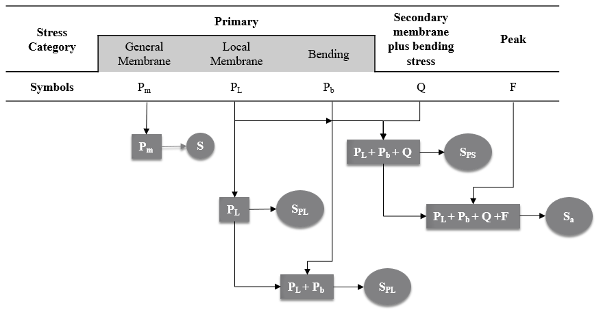
If you are doing stress assessment as per ASME, ASME VIII-2 chart Figure 5.1 provides the stress categorization and their respective allowable limits. Here, stresses are further categorized as primary general membrane, primary local membrane, primary bending, secondary membrane plus bending and peak stresses. This table provides guides for maximum stresses allowed at various different locations. It is used by most of vessel engineer and analyst to predict the component pass or fail judgment.
Though the stress category are clearly mentioned in the chart but it is difficult to interpret the stresses will lie in which category? As we know that membrane stress is average stress but if you refer this table 5.1 of ASME, you might confuse with the terminology and allowable limits used and hence the codes experience and correct judgments are needed to qualify the components. Refer Figure 2 for stress categorization and their limits as per table 5.1 of ASME section VIII-2.
Figure 2: Stress Categorization and Equivalent Stress Limits
Primary Stress: A normal or shear stress developed by the imposed loading which is necessary to satisfy the laws of equilibrium of external and internal forces and moments. The basic characteristic of a primary stress is that it is not self-limiting. Primary stresses which considerably exceed the yield strength will result in failure or at least in gross distortion.
General primary membrane equivalent Stress (Pm): This stresses are found away from junction and are compared with directly with allowable limits.
Local primary membrane equivalent Stress (PL): This stresses are assumed to be at critical locations like junctions, supports, sudden change in cross section, other geometric irregularity, etc. and are compared with SPL (1.5*S). Limits are higher for local membrane due to fact of, additional stresses will come due to irregular sections.
Primary bending Stress (Pb) For example, for a vessel subject to internal pressure with an elliptical head; Pm equivalent stresses occur away from the head to shell junction, and PL and equivalent stresses occur at the junction.
Secondary stress: A normal stress or a shear stress developed by the constraint of adjacent parts or by self-constraint of a structure. The basic characteristic of a secondary stress is that it is self-limiting. Local yielding and minor distortions can satisfy the conditions that cause the stress to occur and failure from one application of the stress is not to be expected.
Examples of secondary stress are a general thermal stress and the bending stress at a gross structural discontinuity.
Peak Stress: The basic characteristic of a peak stress is that it does not cause any noticeable distortion and is objectionable only as a possible source of a fatigue crack or a brittle fracture.
Examples of peak stress are: the thermal stress in the austenitic steel cladding of a carbon steel vessel, the thermal stress in the wall of a vessel or pipe caused by a rapid change in temperature of the contained fluid, and the stress at a local structural discontinuity.
Examples of Stress Linearization
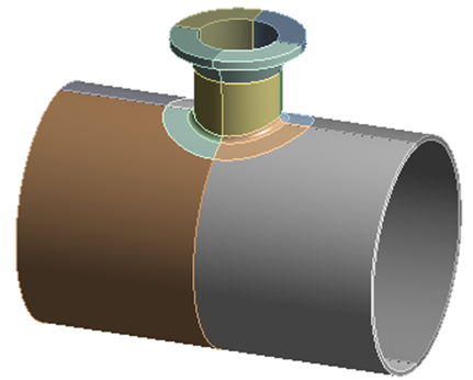
This paragraphs shows, how to perform the stress linearization for nozzle shell junction, refer Figure 3.
Figure 3: Nozzle & Shell
1. Problem Definition: Consider the Nozzle Shell Junction problem. Here the nozzle is welded to the cylinder, refer Figure 1. The materials and weld details should be well define prior to simulations.
2. Meshing: Quadratic (second order) fine and mapped mesh is used to capture the geometry. It recommended that minimum 2 to 3 elements should presents across the thickness of the components to capture the bending behaviour. The FEA results accuracy is depends on the meshing, sometimes mesh convergence and mesh accuracy study is to be done prior to FE analysis.
3. Solution: After mesh model is ready, the next step is to apply loading & boundary conditions. The load in present case is internal pressure as well as compensating pressure at openings (of Nozzle & shell) and one end of the shell is fixed in all DOF. You can either apply compensating pressure or close all the openings. The CP will acts at thrust pressure which compensate the effect of internal pressure at openings. Furthermore, cylindrical constrained are more preferable than fixed supports. Fixed support are more prone to localise stresses.
4. Results Validation: Once solution is converged, the next step is to extract the results and to perform the validations. Validation can be performed by doing simple sanity checks like hoop stress validations & if forces and moments are applied then the reaction should have the same forces and moments at the support locations.
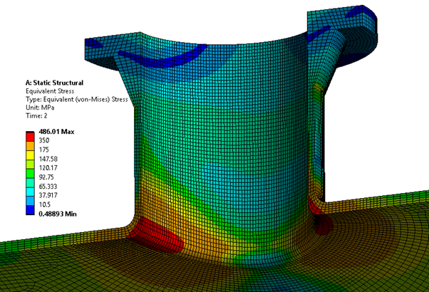
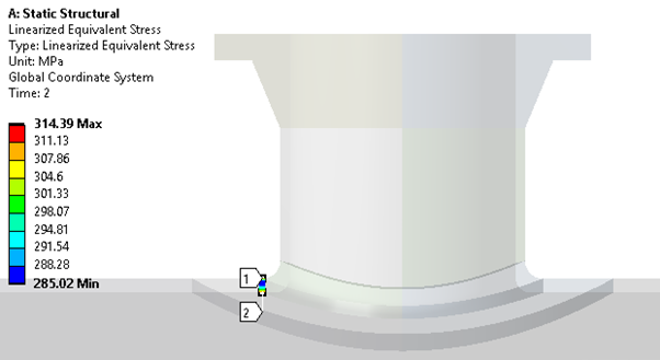
5. Stresses Extraction: FEA program calculates the stresses (normal stresses Sx, Sy, Sz, & shear stresses Txy Tyz, Txz) at each and every nodes and compute with von Mises stress theory which is more commonly used for ductile materials. The Figure 2 shows the equivalent stress plots. The maximum stress is present at the nozzle shell junction location. In order to consider the maximum stresses, it is recommended that SCL should pass this high stress regions.
Most of FEA software’s have provision for SCL or path creation. If you are using ANSYS workbench, then you need to create the construction geometry and then path. You can create this by right click on model (top of the tree in ANSYS mechanical) and then construction geometry and define path. You can create path either by selecting edge of by selection nodes or points of inner and outer surfaces.
It is better to have few (4 to 6) SCL instead one SCL at high stress location, the SCL numbers are based on the number of components need to be assessed. If you are validating whole pressure vessel, in such cases you will need SCL for each components of the vessel. In addition to this, you will need few SCL at away from junction due to the fact, SCL away from junction are general primary membrane stress which is compared with one time allowable limits (1*S) while the SCL at the junctions are general local membrane stress which is compared with (1.5 * s or SPL).
Figure 4: Equivalent (von Mises Stress)
6.SCL Creation: Figure 3 depicts SCL location which is taken at maximum stress location i.e. nozzle shell junction which is straight line passing through inner and outer surface of the shell.
Figure 5: SCL Path
7. Linearized Stress Results:
a. Linearized Equivalent Stress:Results for the respective path can be viewed in the results section through Linearized stress for the SCL path. It shows linearized equivalent stress plots and stress linearization graph. The linearized stress plot legend shows minimum to maximum stress values across the SCL, refer Figure 4.
Figure 6: SCL Linearized Stress
When Linearized stresses are presented, but do you know how does it shows stresses for respective path?
FEA program calculates the stresses values in global coordinates system and when you import stress results for SCL, 6 stress components are read for each node on the SCL. The stress components are aligned with the global coordinate system of the model. The data for each node needs to be translated along the SCL coordinate systems. Sometimes you prefer to have results in local coordinate system along SCL, in that case, FEA program transfer data from global to local coordinate system.
(Sx, Sy, Sz, Txy, Tyz, Tzx) = (Sn, St, Sh, Tnt, Tnh, Tht) for each node
Global Coordinate System Local Coordinate System
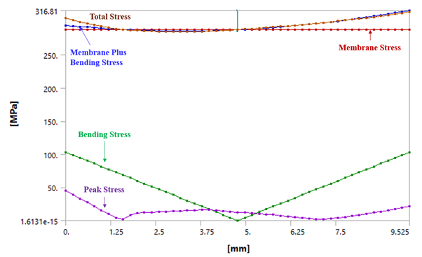
b. Stress Linearized Graph:In stress linearization graph, horizontal axis shows the thickness while vertical axis present stresses. Refer Figure 5 for stress linearization graph of SCL. It represents various stress lines which are varying across the thickness, stresses includes membrane, bending, membrane plus bending, peak and total stresses, etc. By seeing this graph you can easily figure out stress values and its locations across the SCL. In addition to this, you can easily identify that, the SCL is inclined or straight line based on thickness of the component at SCL location. You can cross-check thickness at SCL with thickness mentioned in horizontal line of graph.
Figure 7: Stress Linearization Graph 1
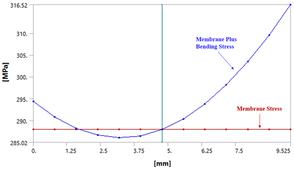
As discussed above, the peak stress is used to find out the fatigue life and membrane & membrane plus bending are used to find out plastic collapse and hence, graph with only membrane & membrane plus bending stresses is used to find out the plastic collapse, refer Figure 6. If you are using ASNYS mechanical then you have provision to increase the number of points in graphs up to 47. It means you will get stress values at 47 locations on the graphs. Generally you should have stress result at all the nodes across the SCL path (if you have 5 second order elements across thickness, then you have 11 nodes for stress results), but ANSYS gives results on additional data points by doing interpolation.
Figure 8: Stress Linearization Graph 2
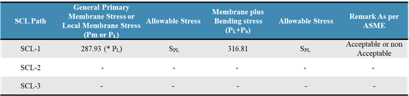
8. Stress Assessment Table: Lastly, the stress assessment table is to be prepared. Here, you can include SCL results for all the path. In present case, we took one SCL at the junction and hence its stress outputs are local membrane stress and local membrane plus bending stress which can be compared with SPL allowable limits. If this SCL values are below SPL limit then, the design is safe if not then design suggestion like local reinforcement pad are recommended. The SPL, allowable limit on local primary membrane and local primary membrane plus bending is referred from ASME Section VIII div.2 codes, which is larger of (1.5*S or Sy based on satisfaction of ASME criteria)
You might have got the answer for this question too, Why to perform stress linearization? If not then refer further below lines….
In case pressure vessel, we are interested to see not only the surface stresses but also through the thicknesses, and furthermore, ASME codes provides allowable stress for various stress components which we will get after doing stress linearization’s.
References:
ASME BPVC Section VIII, Division 2, Part 5, design by analysis, Edition 2017
11 comments
Thanks for the information. It is very helpful. Thanks for sharing.
you did really good job. It is very helpful to every beginner.
Thank you !
can you create a youtube video on how to compare linearized stresses with allowable limits. which you have covered in Webinar I and Webinar II. subscriber would be delighted if you create a video on it.
We already have video on stress linearization…in this we compare the stresses with allowable limits. Please visit grasp engineering YouTube channel. Thanks!
Many thanks for these useful informations. Lot of informations are very detailed to understand clearly, as the conventional code ASME is not easier to interpret.
Thank you !
It was a great tutorial/explanation about the method. I am curious to know how to perform the verification using elastic analysis for protection against local failure. As stated in the code we have to use the principal stresses membrane + bending, however I dont know yet how to perform this using a scrip in ansys. As far as i know, I have found some plug in that can perform this directly in all region of the component.

Thanks for the information. It is very helpful. Thanks for sharing.
you did really good job. It is very helpful to every beginner.
Thank you !
can you create a youtube video on how to compare linearized stresses with allowable limits. which you have covered in Webinar I and Webinar II. subscriber would be delighted if you create a video on it.
We have already few videos on stress linearization, Check one of the video link: https://www.youtube.com/watch?v=iJEVFvChyIQ&t=372s
We already have video on stress linearization…in this we compare the stresses with allowable limits. Please visit grasp engineering YouTube channel. Thanks!
Many thanks for these useful informations. Lot of informations are very detailed to understand clearly, as the conventional code ASME is not easier to interpret.
Thank you !
It was a great tutorial/explanation about the method. I am curious to know how to perform the verification using elastic analysis for protection against local failure. As stated in the code we have to use the principal stresses membrane + bending, however I dont know yet how to perform this using a scrip in ansys. As far as i know, I have found some plug in that can perform this directly in all region of the component.