
What is GD & T ?
GD & T stands for Geometric Dimensioning and Tolerances. GD & T is a language that uses symbols on engineering drawings, engineering tolerances to describe the nominal geometrical variation, geometry requirements for associate features on components or assemblies. It is a common language used by designers, manufacturers, quality engineers to demonstrate, review and efficiently communicate products and their various features. It illustrates the degree of accuracy and precision required for each controlled feature of the parts. It demonstrates symbols, dimensions, tolerances, rules, definitions and conventions that can be used to accurately communicate the functional requirements of the position, orientation, size and shape of each feature of the design model.
GD & T plays a major role in the product life cycle and hence it is widely used by various industries like automotive, electronic, process industry (static equipment), aerospace as well as other manufacturing industries, etc.
Today’s advanced technology, modern design & engineering, new manufacturing methods, optimum design requirements, new competitive product launches required faster and effective way of communication to successfully deliver the end products. GD&T is therefore an exact language which allows designers to transmit their design models according to design aspects and the production department can then use this language to understand design intent while quality uses it to determine configuration requirements through inspection. To make these languages more effective and understandable, some common pool standards are used globally. There are some standards available worldwide that describe the guidelines for GD&T. Most widely used standard is ASME Y14.5 & ISO/TC 213. The ASME Y14.5 provides a fairly complete set of standards in one document while ISO typically addresses one topic at a time.
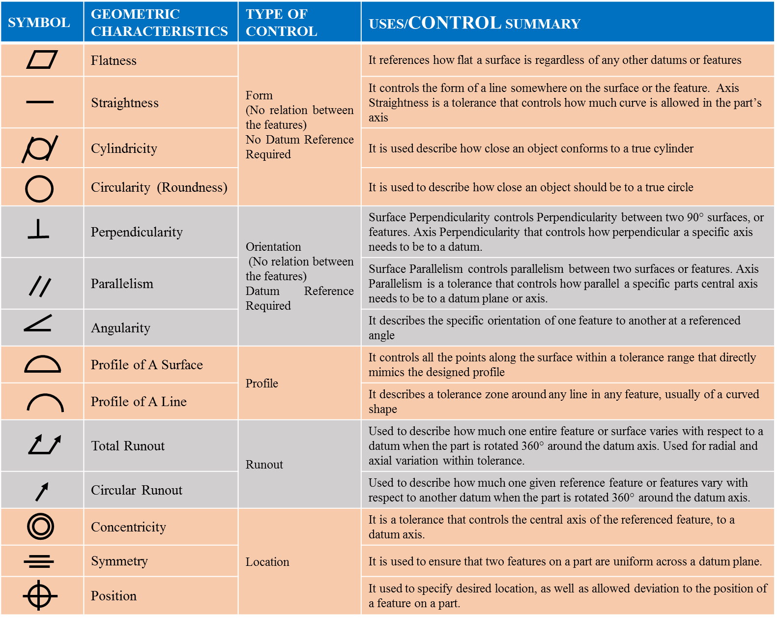
Geometric Tolerancing Symbols
When we talk about GD&T, symbols or geometric characteristics will most often come to peoples minds. There are a total fourteen GD&T symbols mentioned in table 1. GD&T is a feature-based system, and parts are composed of features. Geometric tolerances are applied to features by feature control frames. These tolerancing symbols fall into five groups:
- Form Tolerances: control the “shape” of features and are often used as a refinement of size.
- Profile Tolerances: describe the three-dimensional tolerance zone around a surface:
- Orientation Tolerances: concern dimensions that vary at angles, control the “tilt” of features and are always associated with basic angle dimensions, often used as a refinement to location.
- Location Tolerances: define feature locations using linear dimensions. Position locates and orients the median plane or axis of features of size. Profile locates feature surfaces. Profile is the most powerful characteristic of all, and also controls orientation and form.
- Runout Tolerances: define the amount by which a particular feature can vary with respect to the datum.
Datum in GD&T
A datum is the exact plane, axis or point location that GD&T or dimensional tolerances are referenced to. It acts as an anchor or starting point for the whole part; where the other features are referenced from. Nearly most GD & T symbols except form tolerances (straightness, flatness, circularity, and cylindricity) can use datums to help specify the geometric control that is needed on the part.
How Datum Features are Shown on a Drawing
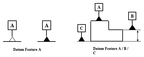
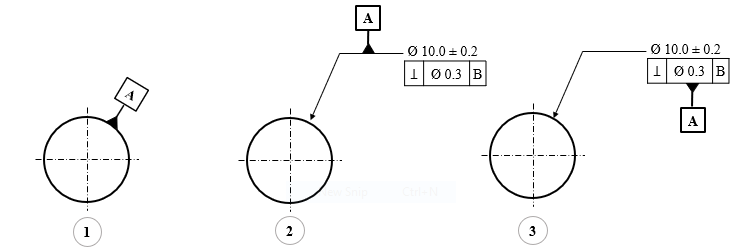
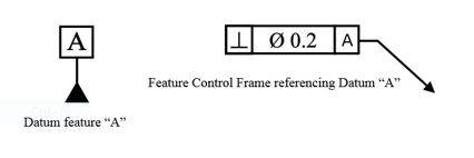
The datum features on a drawing are denoted with a series of capital letters, which are shown in boxes and tied to the datum feature with a black triangle. This letter will also be presented in any feature control frame that uses this datum feature as a reference. A feature control frame can reference multiple datums at once and each one can be referenced as many times as per need. Datum symbols use either a white or black triangle as shown in Figure 1. The letters indicating the datums are always oriented to the direction the reader looks at the drawing.
As per definition, Datums are planes, axes, or point locations, and that’s exactly how they show up on a drawing. Let’s discuss how different types of features are called out on engineering drawings.
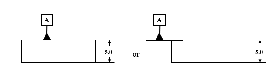
On a Surface (Plane)
We can place the datum symbol either on the surface or on one extension line from the surface as shown in Figure 2. For any surface other than a round cylinder, the datum is strictly on the side where the symbol is shown. However if the part is round like a cylinder, the datum would be the entire surface of the cylinder.
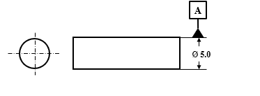
On an Axis
For Axis control, the symbol must be placed on the dimension of a diametric tolerance as shown in Figure 3. This means that the datum is actually the central axis through the feature, and not the feature surface itself. This type is common with any GD&T symbol that can have axis control like concentricity, perpendicularity or runout tolerances.
On a Point or Hole’s Axis
To establish a datum axis on a feature such as a hole, there are different ways to place the datum symbol. Refer figure 4 showing three different ways for datum A placement on drawings:
- Placed directly on the hole. It is of course referring to the axis and not the surface of the hole
- Placed on the leader pointing to the hole as it is in the middle case.
- Placed on the Feature Control Frame for the hole.
Datums & Datum Features & Datum Target
Datum and datum features are important terms in GD&T. Though both the terms seem to be similar but differences exist between them in terms of geometrical concept.
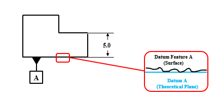
A Datum is a perfect point, line, plane or surface but only exists theoretically. However a Datum Feature is a tangible surface, point or axis on a part where that theoretical datum is located. In the real world the part surfaces are never 100 % accurate (perfectly flat) but some minor waviness, bumps exist. Let’s discuss through a simple example. Consider a step block with bottom zoom face view as shown in Figure 5. Here, the blue line represents the datum and black wavy line forms the datum feature. It means, we can call features a perfect line which exists theoretically & only simulated by Measurement Equipment (Gauge pins, Granite slabs, angle plates, etc) while the actual line, real tangible features on a part with waviness or imperfection are datum features where the measurement equipment would physically touch or measure.
Generally in design and manufacturing “datum” covers everything just for simplicity. However as a GD & T engineer, it is important to know the differences between datum and datum features.
Lastly, you may also come across the term Datum Target, which is defined as, “A specified point, line, or area on a part used to establish a datum.”
Feature Control Frame:
Feature control frame is used to describe the condition and tolerances of a geometric control on parts feature. One feature frame describes only one message or tolerance information if two symbols are necessary then two feature frames are required. The feature control frame consists of following information:
- Geometric characteristic symbol
- Tolerance zone type and dimensions
- Tolerance zone modifiers: features of size, projections…
- Datum reference (if required by the GD&T symbol)
- Material requirement, etc.
Above information used to determine geometric tolerance needed on the part, the specification requirement and its measurement.
- Leader Arrow: This arrow represents the feature that the geometric control is placed on. If this arrow is shown on a circle (diametric dimension) then axis controls are provided, if the arrow points to a surface then surfaces are controlled with respect to the defined GD&T dimension. The arrow is optional but helps clarify the feature being controlled.
-
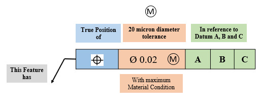
Geometric Symbol: The first compartment of a feature control frame contains one of the fourteen geometric characteristic symbols. This is where your geometric control is specified. The respective symbol will specify the requirement for the feature, such as, “this feature must be flat,”.
-
Diameter Symbol (if required): The second compartment of a feature control frame contains the total tolerance (not a plus/minus value) for the feature. If the geometric control is a diametrical tolerance then the diameter symbol (Ø) will be in front of the tolerance value.
-
Tolerance Value: It represents the tolerance value. The unit is as per geometry sheet (mm).If the tolerance is a diameter you will see the Ø symbol next to the dimension signifying a diametric tolerance zone.
-
Feature of Size or Tolerance Modifiers (if required): Here a material condition modifier such as MMC (maximum material condition), LMC (Least material condition), and CZ (common [tolerance] zone) are placed in the feature control frame as per tolerance required. If the feature has size, and no modifier is specified, the default modifier is RFS. If the feature has no size, such as a plane surface, then the modifier is not applicable.
-
Primary Datum (if required): The third and following compartments of a feature control frame contain the datum feature reference, if required. For example, if a location tolerance like position is specified, the datum feature references are usually required however if a form tolerance, such as flatness or straightness, is specified, then no datum feature reference is allowed. If a datum is required in GD&T then this is the main datum used for the control. The datum letter corresponds to a feature marked in the part with the same letter. This is the datum that must be constrained first when measuring the part as the order of the datum is important for measurement of the part.
-
Secondary Datum (if required): If a secondary datum is required, it will be to the right of the primary datum. The datum letter corresponds to a feature marked in the part with the same letter. The order of precedence for datum has significance, reading from left to right as primary, secondary, and tertiary. The primary is the first feature contacted (minimum contact at 3 points), the secondary feature is the second feature contacted (minimum contact at 2 points), and the tertiary is the third feature contacted (minimum contact at 1 point). During measurement, this datum is fixated after the primary datum.
-
Datum feature Modifier (if required): In some cases, the datum feature modifiers like MMB or LMB may be applied to the datum feature. The default modifier is Regardless of Material Boundary (RMB). The modified condition of the datum feature (MMB, LMB, RMB) defines the size or condition of the datum feature simulator.
-
Tertiary Datum (if required): If a third datum is required, it will be to the right of the secondary datum. The datum letter corresponds to a feature marked in the part with the same letter. During measurement, this datum is fixated last.
How to read Feature Control Frame ?
The feature control frame forms the sentences as per defined GD & T tolerances when you will read. Figure 6 shows the reading of the feature control frame.
Summary:
The Geometric dimensioning and tolerances (GD&T) are used to communicate and interpret the technical information on engineering drawings. The design part and CAD models are perfect geometries but in actual, manufactured parts are not perfectly accurate, the proper use of GD&T can improve quality and reduce time and increase productivity. Key advantages of GD&T are:
- GD & T is a common pool as international standards ensure clear communication of detailed information throughout the complete product life cycle from design, CAD Modeling to manufacturing of the parts.
- The ASME Y14.5 is the most widely used standard that establishes symbols, definitions, and rules for geometric dimensioning and tolerancing.
- GD & T is an effective way of communication for third party vendors, parts suppliers or for the customers during manufacturing of any product or part.
This article covered the basic concepts of GD&T, difference symbols of tolerancing, datum and datum features representation on drawing, feature control frames, etc.