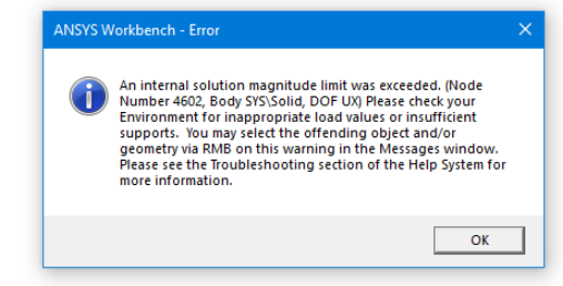
Error 2:
An internal solution magnitude limit was exceeded. (Node Number 4602, Body SYS\Solid, DOF UX) Please check your Environment for inappropriate load values or insufficient supports. You may select the offending object and/or geometry via RMB on this warning in the Messages window. Please see the Troubleshooting section of the Help System for more information.
Solution:
This error (Refer figure 1) is mainly because of rigid body motion due to large gaps between the connecting bodies or parts. When there is a gap between the connecting parts or bodies, the relative motion or load transfer does not happen and hence it leads to flying of the bodies, resulting in internal solution magnitude exceeded. In such a scenario, you will need to define contact with sufficient pinball region.
Sometimes though you includes different bodies in single parts (Form a new part in ANSYS design modeler or Spaceclaim), but still you will notice few bodies are not connected with each other which results in error while performing the simulations. In such cases, you can easily find out such bodies with a connection visibility option or with mesh connectivity in ANSYS. Once you will identify flying bodies, then you need to create connection between them either by using mesh connection or defining contact with sufficient pinball. Thus error will be eliminated while performing simulation.
Examples:
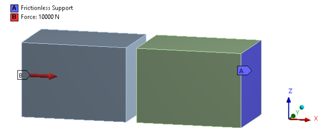
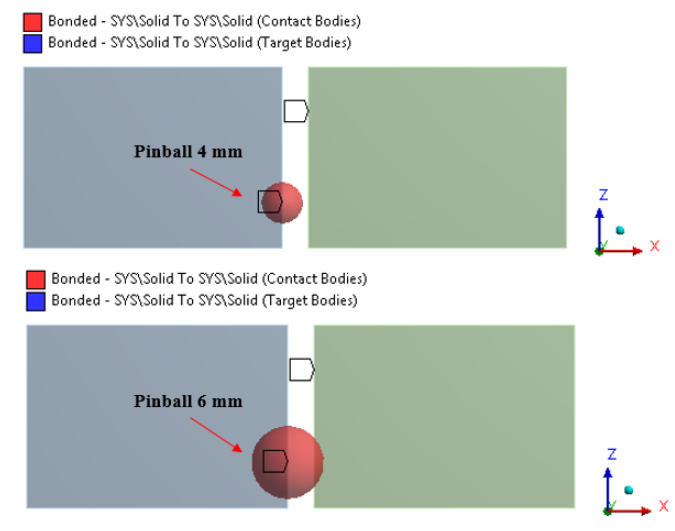
Consider two solid blocks 5 mm away with each other, one block is applied with force while the other block is provided with frictionless support as shown in figure 2. When you try to solve this problem without contact or with contact & pinball region less than the gap (4 mm), you will come across the above error. So you will need to define pinball radius more than the distance between the two parts so that both bodies will come in contact with each other. Refer figure 3 with pinball radius.
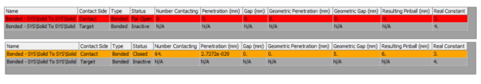
Contact tool :
To understand if the contacts are closed or not, you can use the contact tool. Right click on connection in ANSYS workbench mechanical and insert the contact tool. Contact tool generate the initial information of the contact status. It will display the initial status for all the contact used in the simulation. You need to right click on the contact tool and generate initial contact results. It will display all contacting elements, gap, penetration and resulting pinball for the contacts. You can easily segregate whether the contact is closed or open. If the color is red or yellow means contact is open and when color is grey and yellow, the contact is closed. Based on this initial contact tool information you can easily prevent the rigid body motion error. Figure 4 shows the contact tool initial information snapshot for open (red contact) and closed contact (yellow color).